|
|
 |
 |
SMALL EMC FACILITY
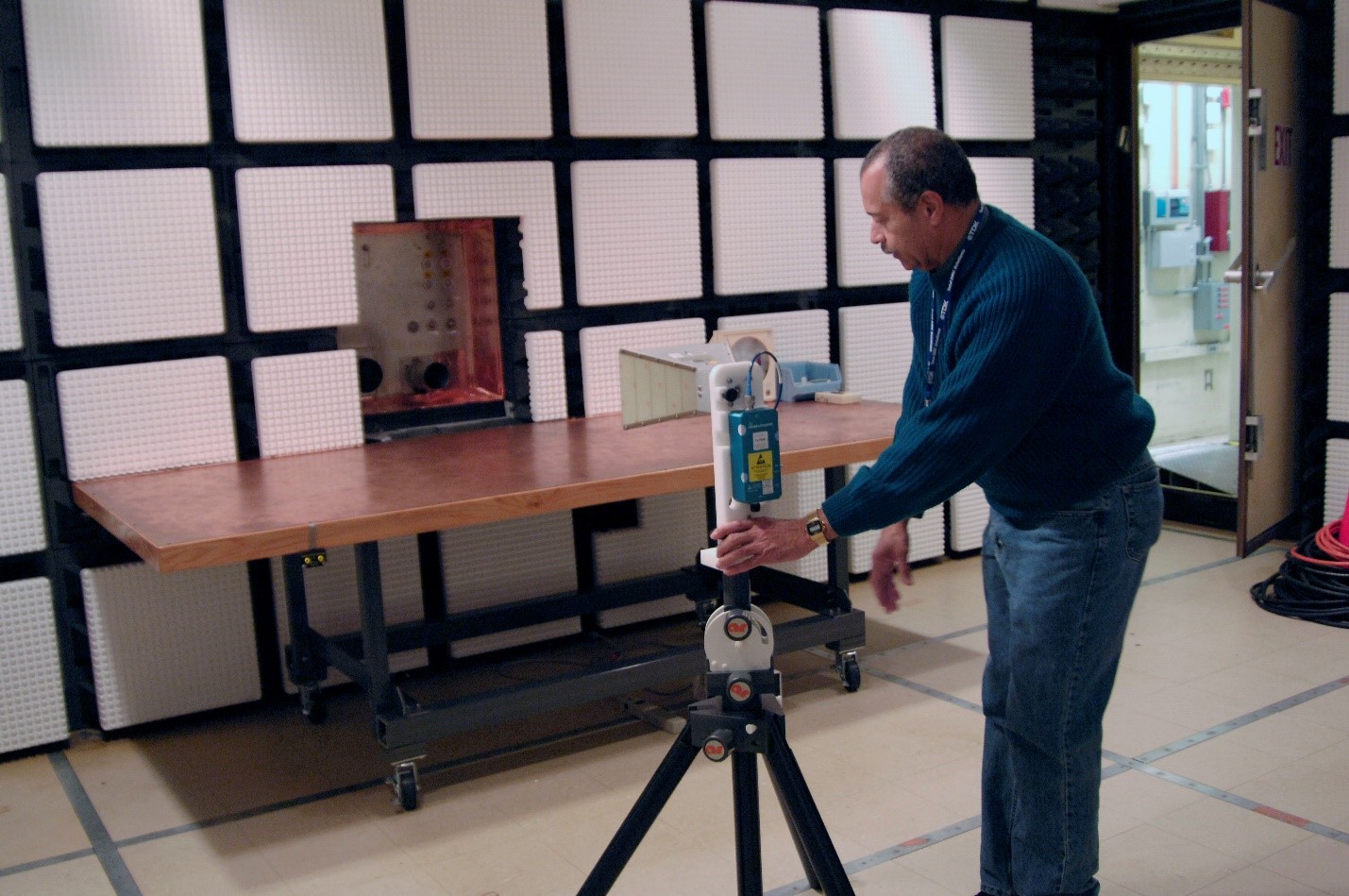
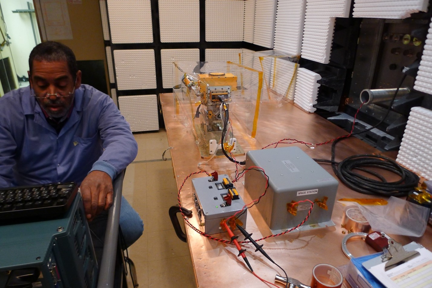
Description:
This facility consists of three contiguous, electromagnetically shielded enclosures and is designed for either small satellite or sub-assembly EMI testing from 10 kHz to 40 GHz. These individually shielded enclosures include the semi-anechoic Test Room, the EMC Control Room, and a Ground Support Equipment (GSE) Room. A 2.5m long, 1m wide, copper-clad test item mounting bench and cable access panel are located on the wall separating the Test Room from the GSE Room.
Mode of Operation:
Small test articles are installed in the Test Room and bonded to either the copper workbench or to the test article holding fixture and the metallic floor. Interconnecting cables between the test article and its ground support equipment are connected through feed-through connectors mounted on the penetration plate to reduce common mode emissions from the GSE racks.
Test Area Anechoic Characteristics:
The Test Room walls and ceiling are covered with ferrite tiles and TDK IP-045 closed cell Styrofoam absorbers, which provide a minimum of 20 dB absorption, above 500 MHz, of normally-incident electromagnetic waves. Field measurement accuracy is thereby enhanced compared to shield room facilities that lack the anechoic material, and radiated susceptibility test signals are controlled with improved signal-to-noise ratios.
Physical Characteristics:
GSE room: 4m (L) x 2m (W) x 3m (H), Personnel door: 1m (W) x 1.7m (H)
Test area room: 5.5m (L) x 5m (W) x 3m (H), Equipment door: 2m (W) x 2.2m (H)
|
LARGE EMC/EMI FACILITY
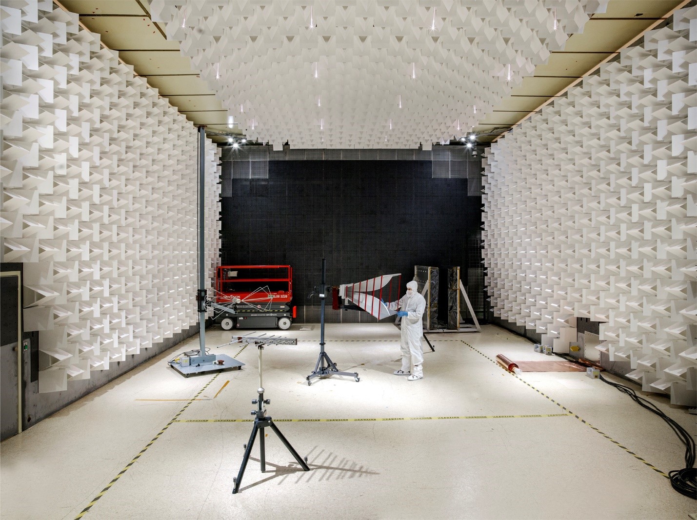 Description:
The large EMC Facility is designed for testing relatively large satellites requiring a high level of contamination protection. This facility consists of three contiguous, electromagnetically shielded enclosures: the class 10k Test Enclosure, the EMC Control Room, and a Ground Support Equipment (GSE) Room. A 2m square fiberglass table with a copper ground plane is available for box/subsystem level testing when required.
Mode of Operation:
The test article is installed inside the class 10k Test Enclosure and bonded to the chamber using a copper strap maintaining a 6:1 (L:W) ratio, which is bonded to a dedicated chemical ground rod to isolate the EMI lab from any unwanted electrical noise generated in the I&T complex. Ground support equipment connections are made through an access panel between the GSE Room and the Test Enclosure either by using a waveguide-below-cutoff cable duct, project-specified panel-mounted connectors, or a set of connectors that duplicate the thermal-vacuum chamber connections (to allow commonality of cable harnesses). The EMC instruments are also connected through an access panel connecting between the Control Room and the Test Enclosure.
Test Area Anechoic Characteristics:
The Test Area enclosure is maintained to a class 10k cleanliness level which is lined with ferrite-tiles and Panashield HYB-NF-12 RF absorber which provide a minimum of 20 dB absorption, above 300 MHz, of normally-incident electromagnetic waves. In addition, we have 4x portable walls lined with TDK IS-015 RF absorber with better RF absorption characteristics. In addition, with have Cummings Microwave C-RAM absorber for use with high power transmitters.
Physical Characteristics:
GSE room: 6.7m (L) x 5.2m (W) x 3.2m (H),
Personnel Door: 2m (W) x 2.5m (H)
Test Enclosure Size: 12m (L) x 10m (W) x 6.7m (H)
Shielded Enclosure/Ferrite Tiled Door Size: 5.86m (W) x 5.6m (H)
|
Portable EMI Testing
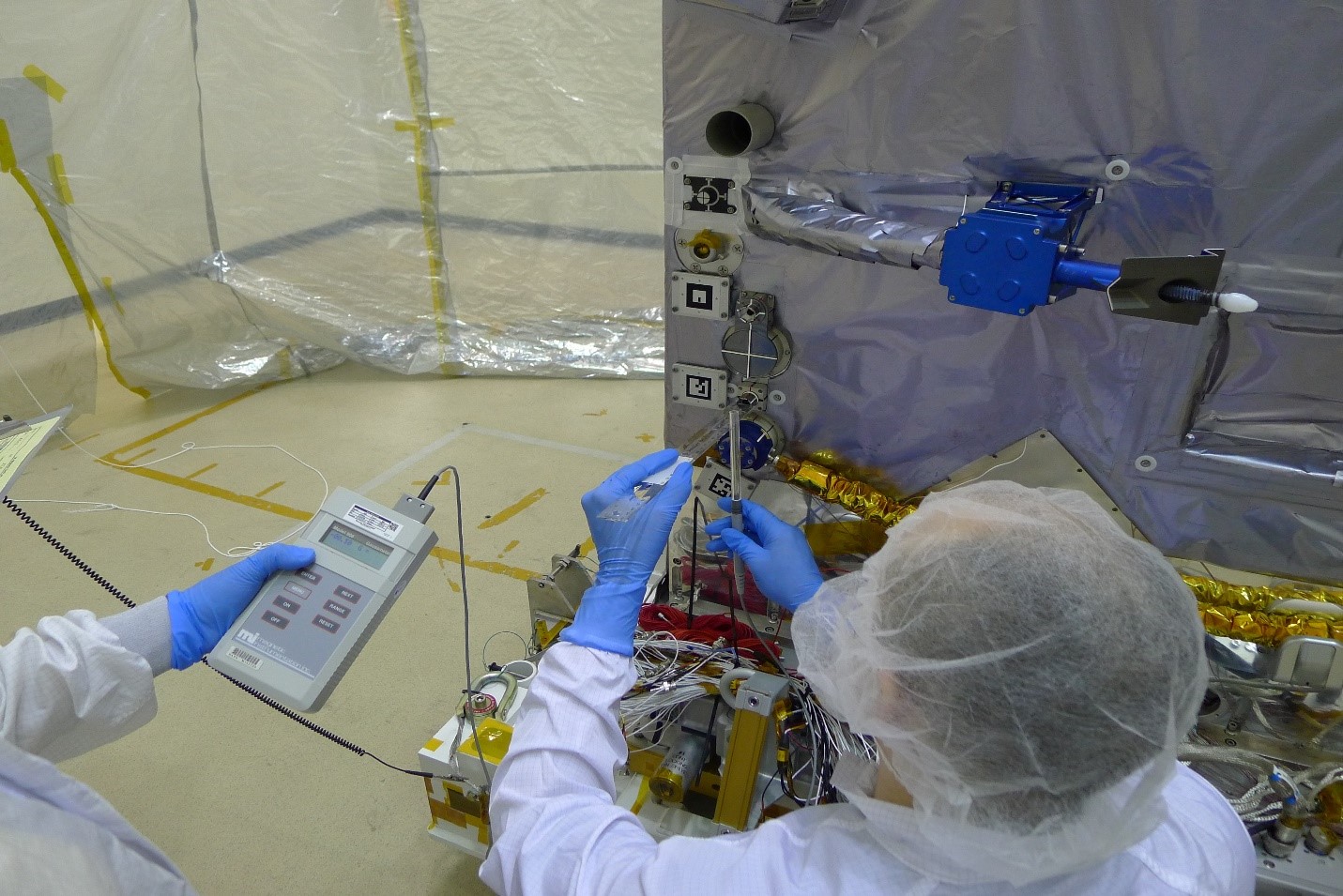
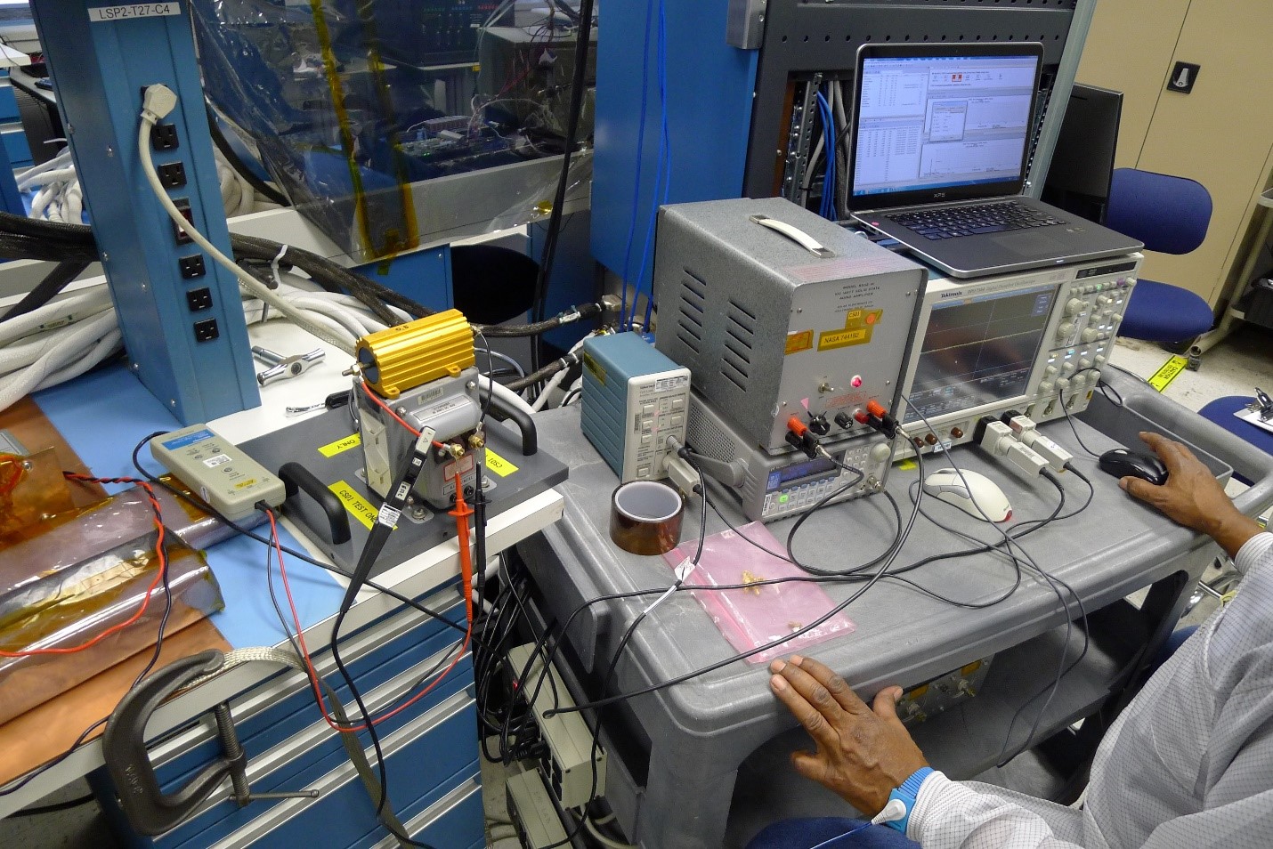
Description:
Workbench EMC measurements are simple, inexpensive pre-compliance tests that a product designer can have performed early in the development phase of a product in order to obtain an indication of the EMC performance of that product.
Purpose:
The advantages of early EMC testing during the design phase of a product include:
- Increased probability of passing the final compliance test
- Minimizes the number of retests required for compliance at an EMC test laboratory
- Eliminates surprises late in the design (due to EMC failures)
- Insures that EMC considerations are part of the original design, not add-ons
Test Capabilties:
The tests performed are usually conducted in nature but some radiated testing is possible, usually magnetic in nature. These tests cover all MIL-STD-461C/G EMI as well as International Space Station (ISS) EMI and PQ testing. If needed and the space is available, we can bring a shielded tent enclosure over to help reduce any radiated signals in the environment. The tent enclosure versus EMI chamber is evaluated on a case by case situation.
|
MAGNETIC TEST SITE
Description:
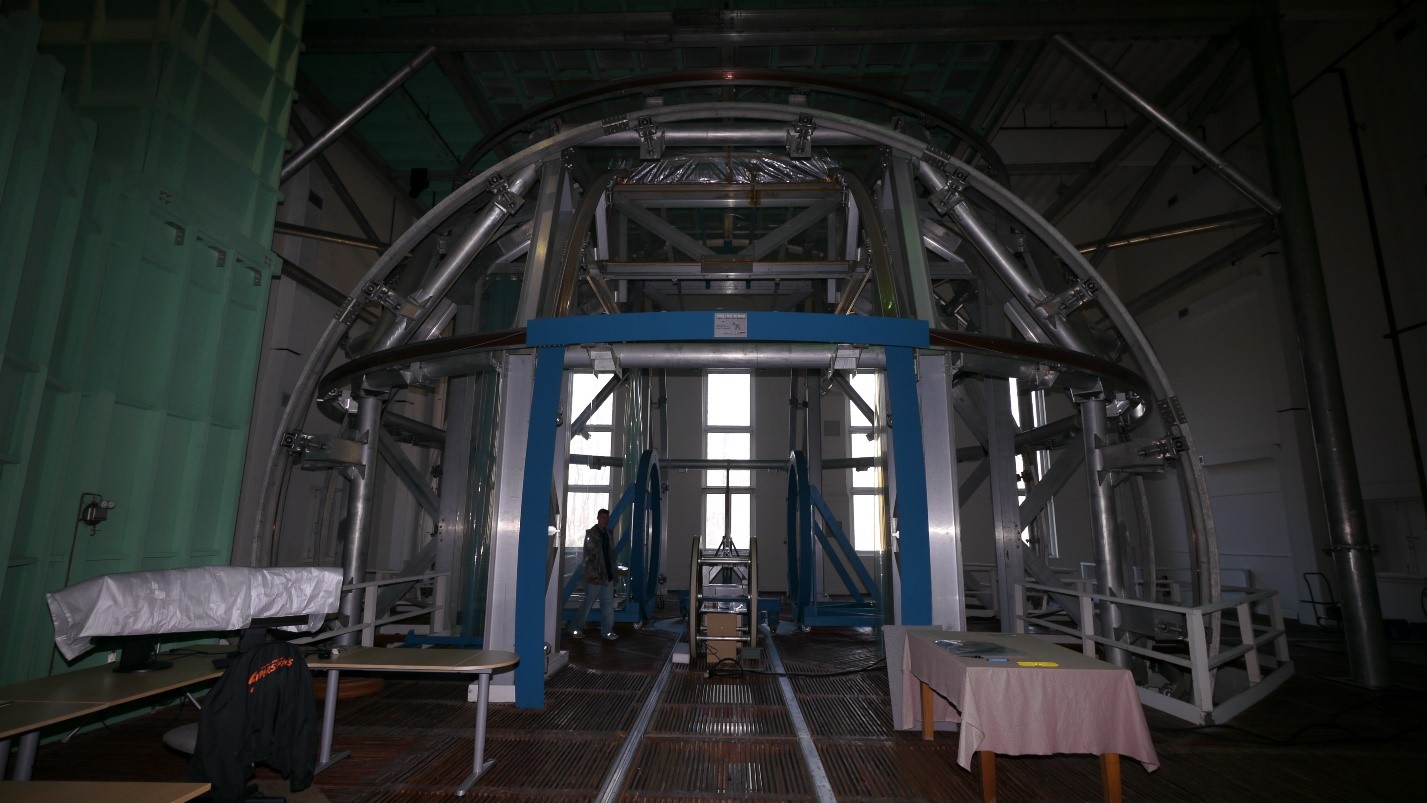
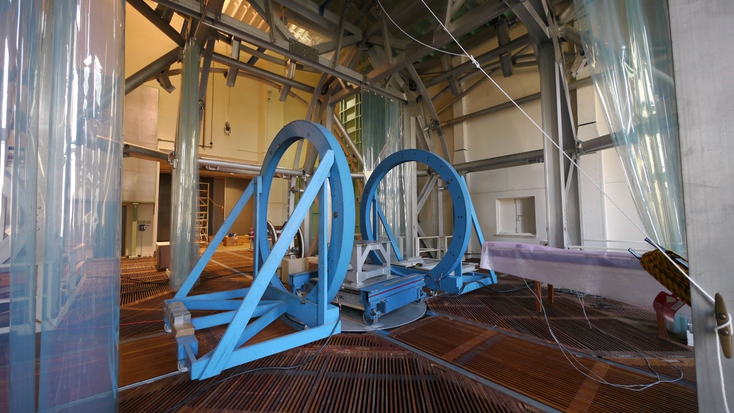
The Spacecraft Magnetic Test Facility (SMTF) 13m coil system is one of the three known spherical coil systems of this size in the world. Its geomagnetic field cancellation system is capable of cancelling the Earth's magnetic field within a 1.83m (6’) diameter sphere. The SMTF also has a set of 2.9m diameter Helmholtz coils available for perming and deperming spacecraft, and 1.22m and 1.83m diameter coils for magnetically cleaning smaller test items.
Magnetic Dipole Moment Testing:
Zero field is first established in the center of the coil. A reference standard proton magnetometer is used to calibrate the coils. For each measurement sequence, the test item and facility dolly are moved to the center of the coil. As the dolly is rotated 360 degrees, three-component magnetic field data is obtained at 10-degree increments. The data are then stored in the computer for immediate display and processing. If the test item exceeds its test limit, compensation magnets can be developed to reduce the dipole moment to acceptable levels.
Spacecraft Magnetometer Calibration:
Initial setup is similar to magnetic dipole moment testing. The test item is positioned in the center of the coil and aligned with the coil axes. Static and dynamic fields are generated to establish linearity, frequency response, zero offset, and alignment characteristics of the test item. The data system can be used to collect, store, and display test parameters.
Parameters:
Static Field:
Magnitude: ± 60,000nT
Resolution: ± 0.1nT
Noise: ± 0.5nT
Homogeneity: 0.001% (1.83m, 6’ diameter spherical volume)
Dynamic Field:
Magnitude: ± 60,000nT
Resolution & Stability: ± 2% Frequency: 0 to 100 rad/sec
Physical Characteristics:
Coil access opening: 3.05m (W) x 3.05m (H)
Building access opening: 4.27m (W) x 4.57 (H)
Hoist lifting capacities (4): 4,536 kg , 2,722 kg, and two each 2,268 kg
|
Portable Magnetic Testing
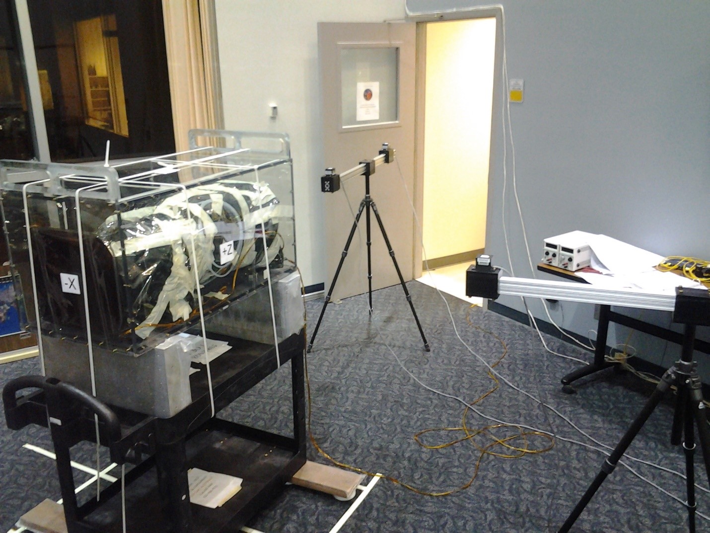
Magnetic Dipole Moment:
Dipole moment testing can be performed in remote environments as long as the instrument is a provided a way to rotate about its own center. Ideally, the device used for rotation is made from non-ferrous components. In the event that it is not, it will be required to test the device used for rotation without the instrument mounted on it. During testing control of the environment is crucial and there should be no moving magnetic fields. It is recommended that this testing is done at night when interference from normal lab activities is lowest.
Magnetic Characterization (Static & Dynamic):
The instrument can be characterized for its permanent magnetic field in a remote environment by moving the instrument into position while all of the items within the environment remain static. This the test as would ideally be performed with a non-ferrous dolly to move the instrument. If that is not possible can be done but the dolly would need to be measured without the instrument mounted to it.
The magnetic field generated while the instrument is operating can also be characterized in a virtual strip chart. This data is saved to a database and can be linked to scripting logs used to operate the instrument. As with all remote testing this all depends on no external moving magnetic fields.
Parameters:
Magnitude: ± 65,000nT
Resolution: 1.989nT
Noise: ± 2.5nT
Frequency: DC to 10 Hz
|
|
 |
|

